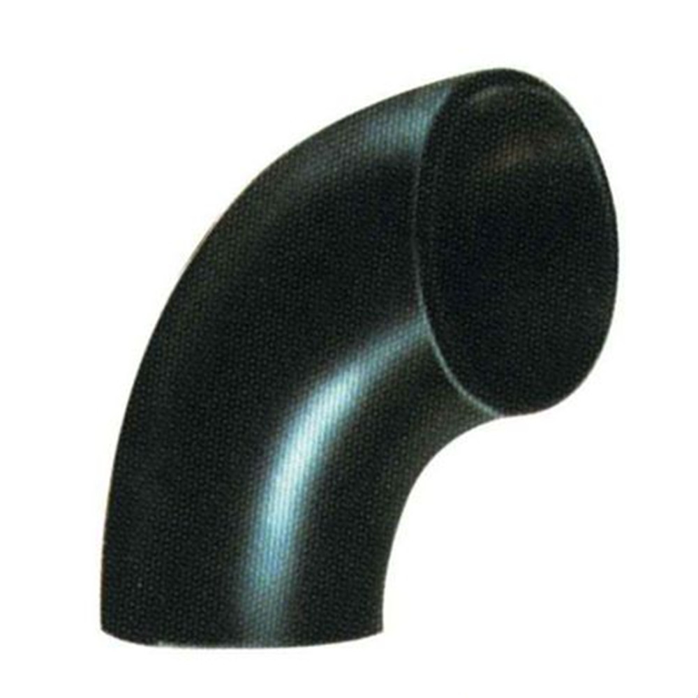
Seamless Boiler Bend,Stainless Steel Boiler Bend,Boiler Tube Bending,U Bent Tube Boiler Jinan Yuanda Power Equipment Co.,Ltd. , https://www.jnyuandaboiler.com
2 Introduction to the sensor A sensor is a device or device that can sense the specified measurement and convert it into a usable output signal according to a certain law. The input signal (measured) is often non-electricity, and the output signal is often an easily-processable quantity of electricity. Voltage and so on.
There are many kinds of sensors, and the classification standards are different. The name is not the same. Common resistance sensors, inductive sensors, capacitive sensors, temperature sensors, piezoelectric sensors, Hall sensors, thermocouple sensors, photoelectric sensors, digital Position sensors, etc. The sensors used in CNC machine tools include photoelectric encoders, linear encoders, proximity switches, temperature sensors, Hall sensors, current sensors, voltage sensors, pressure sensors, liquid level sensors, resolvers, inductive synchronizers, and speed sensors. Mainly used to detect position, linear displacement and angular displacement, speed, pressure, temperature and so on.
3 The requirements of the CNC machine tool for sensors (1) High reliability and strong anti-interference;
(2) Meet the accuracy and speed requirements;
(3) Easy to use and maintain, suitable for machine tool operating environment;
(4) Low cost.
Different kinds of CNC machine tools have different requirements for sensors. In general, large-scale machine tools require high speed response, and medium-sized and high-precision CNC machine tools mainly require precision.
4 Displacement detection The displacement detection sensors mainly include pulse encoders, linear encoders, resolvers, and induction synchronizers.
4.1 Pulse Encoder Applications Pulse encoders are angular displacement (rotational) sensors that convert mechanical angles into electrical pulses. Pulse encoder can be divided into three types: photoelectric, contact and electromagnetic. Among them, there are many photoelectric applications.
In Figure 1, the end of the X-axis and Z-axis are equipped with photoelectric encoders for angular displacement measurement and digital speed measurement. The angular displacement can indirectly reflect the linear displacement of the carriage or tool holder through the lead screw pitch.
4.2 Application of Linear Gratings Linear gratings are produced using the transmission and reflection of light. They are often used for displacement measurement, have high resolution, and have higher measurement accuracy than photoelectric encoders and are suitable for dynamic measurements.
In the feed drive, the grating scale is fixed on the bed, and the generated pulse signal directly reflects the actual position of the carriage. The servo system that uses the grating to detect the position of the table is a closed-loop control system.
4.3 Application of resolver A resolver is an inductive micromotor with a continuous function of output voltage and angular displacement. The resolver consists of a stator and a rotor. Specifically, it consists of a core, two stator windings, and two rotor windings. The primary and secondary windings are placed on the stator and rotor, respectively, and electromagnetic coupling between the primary and secondary windings is performed. The degree relates to the rotation angle of the rotor.
4.4 Induction synchronizer application Induction synchronizer is made using the principle that the mutual inductance of two planar windings varies with position. Its function is to convert the angle or linear displacement into the phase or amplitude of the induced electromotive force, which can be used to measure straight line or angular displacement. According to its structure can be divided into two kinds of linear and rotary. The linear induction synchronizer is composed of a fixed length and a sliding rule. The fixed length is installed on the machine bed. The sliding rule is installed on the moving part and moves along with the worktable. The stator of the rotary induction synchronizer is a fixed disc. Rotor For rotating discs. Induction synchronizer has the advantages of high precision and resolution, strong anti-interference ability, long service life, simple maintenance, long distance displacement measurement, good processability, and low cost. Linear inductive synchronizer is widely used in static displacement and dynamic measurement of large displacements, such as coordinate measuring machines, programmable CNC machine tools, high-precision heavy machine tools, and machining center measuring devices. Rotary induction synchronizers are widely used in turntables of machine tools and instruments as well as various rotary servo control systems.
 Boiler Tube Bend are made form tight radius thick wall tubes used in the boiler industry. We manufacture these heavy-duty machines equipped with a clamping device, which locks the tube into the pressure die and allows the tube to be forced thus reducing wall thinning and ovality.
Application of Sensors on CNC Machine Tools
Due to the characteristics of high precision, high speed, high efficiency, and safety and reliability, CNC machine tools are rapidly gaining popularity in enterprises in the renewal of manufacturing technology and equipment. A CNC machine is an automated machine equipped with a program control system that allows the machine to move and process parts based on programmed programs. It combines the latest technologies in machinery, automation, computer, measurement, and microelectronics, and uses a variety of sensors. This article describes the application of various sensors on CNC machine tools.