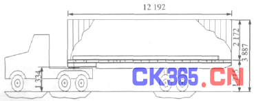
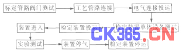
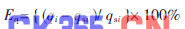
Flow is a very important parameter in the industrial production process. During the development of an oil and gas field, the flow measurement runs through the entire production process, and any one of the links is inseparable from the flow measurement. Flow measurement is also an important basis for corporate economic accounting. Accurate and reliable flow measurement is an important means to ensure that the enterprise obtains the best benefits and guarantees normal and efficient production. However, flow measurement is an extremely complex technique, and its measurement accuracy is affected by many factors such as the physical properties of the medium, installation conditions, operating conditions, flow characteristics, and environmental changes. Therefore, it is necessary to establish a unified method for verifying the accuracy of the flow measurement instrument to ensure that the flow meter meets the requirements of the production process and guarantees trade equality. The natural gas flow measurement in Changqing Oilfield adopts orifice flowmeters, intelligent precession flowmeters, turbine flowmeters, ultrasonic flowmeters, etc., in which the internal metering is based on orifice flowmeters, and the measurement of foreign trade basically uses multichannel gas ultrasonic flow. meter. Changqing Oilfield Company's natural gas metering station is responsible for the verification of gas field flowmeters. The verification of the orifice flowmeters always follows the geometric verification (inspection) method; the intelligent precession flowmeters mostly use laboratory flow verification devices for off-line verification, using air and low pressure. Natural gas is used as medium for negative pressure verification; Ultrasonic and turbine flow meters are tested in offline form. With the continuous development of real-flow verification technology, Changqing Oilfield has gradually established a complete natural gas flow verification system, which has significantly improved the reliability and credibility of the entire metering system. In 2004, Changqing Oilfield introduced the mobile on-line real-flow verification device for the first time. In 2008, it also built a fixed online real-time calibration system, which enabled Changqing Oilfield's natural gas measurement system to realize on-line real-flow verification and calibration. 1 Application of mobile online real-time verification device 1.1 Application Background With the continuous expansion of Changqing gas field production scale, the number of flow detection instruments in the production process is increasing. Due to the dispersion of gas field stations, a mobile verification device is needed. At present, the widely used orifice flowmeters are susceptible to many problems such as non-standard installation pipelines, actual gas flow characteristics, improper pressurization piping, and fouling of the orifice plates, and the measurement accuracy is low. Therefore, it is necessary to use mobile online flowmeters. The flow verification device is updated. 1.2 Standard Table Selection The gas turbine flowmeter has the characteristics of high measurement accuracy, stable performance, less influencing factors, and wide range ratio; multi-channel gas ultrasonic flowmeter has high accuracy, applicable flow range, no wear, no moving parts, no pressure loss , Small maintenance and other characteristics. Therefore, a 0.5-level high-precision gas ultrasonic flowmeter was selected as the field comparison table, and a 0.2-grade gas turbine flowmeter was selected as the standard table. 1.3 verification process and characteristics (see Figure 1) Figure 1 Verification process The verification method is double standard meter serial method, and the two standard meters should be different working principle instruments. Design a DN250mm inlet line and install gas ultrasonic flowmeter; design two gas outlet pipes, according to the Changqing gas field in the use of natural gas flow metering instrument, all the way to DN300mm, another way to DN100mm, and install gas turbine flowmeter as Standard table with electric control valve installed behind the table. The characteristics of this verification method are: (1) Change the original design header T-connection to elbow connection. (2) A plate flow regulator is installed at a diameter of 10 times in front of the watch; an ultrasonic flowmeter is preceded by a 20-fold diameter straight pipe section, and a turbine flowmeter is preceded by a 15 times-diameter straight pipe section. (3) The flow regulating valve is installed after the outlet piping table, and the on-line full-component analyzer is installed after the inlet piping table. (4) Skid-mounted integration, complete vehicle calibration (CEESI of Colorado Engineering Laboratory Co., Ltd. issued a real-flow test document). 1.4 Technical Specifications Total uncertainty: ≤ 0.6% when manufacturing is completed without any modification to the entire device, and ≤ 0.5% after calibration is corrected. Operating conditions flow range: 50 ~ 5000m3 / h. Design pressure: 6.3 MPa; working pressure: 4.0 to 6.0 MPa. The entire device pressure loss: not more than 4% of the working pressure. Detection instrument accuracy: ultrasonic flowmeter ≤ 0.5, turbine flowmeter ≤ 0.2, temperature transmitter is ± 0.1 °C, pressure transmitter ≤ 0.075 level, compression factor calculation accuracy ≤ 0.3. Explosion-proof grade: dIIBT4. 1.5 Basic configuration of the verification device (see Figure 2) Figure 2 Overall illustration of the verification device The whole set of equipment mainly includes: standard metering and measurement straight pipe section, chromatographic analysis system, flow computer, data acquisition and processing system, flow regulation control system, skid seat and process connecting pipe fittings, supporting instruments and transmitters, control room, chassis vehicle and Protective box and so on. The whole set of equipment is designed once. The verification equipment is assembled into a skid and firmly fixed with the chassis. In the field operation, the whole set of equipment, in addition to the process connection pipe fittings, does not need to make any relative movement (placed on the chassis car), and only needs to be connected with the on-site calibration reserved port. The dimensions of the complete set of equipment (including chassis vehicles) are: 12.192m (length) × 2.4m (width) × 3.887m (height). The tractor uses a chassis manufactured by AMERITRAIL, USA, with a total mass of 23 tons. The tractor is used for transporting trailers and carrying calibration equipment. The ND4180D291BJ heavy-duty vehicle was produced by the North Mercedes-Benz. The maximum traction of the vehicle is 31t, and the total mass of the two vehicles is 28t. 2 Application of Fixed Online Real Flow Calibration System 2.1 Project Construction Overview Because the established foreign trade metering calibration reservations in the gas field do not meet the requirements of the mobile online real-flow verification device technology connection requirements, the metering ports were correspondingly reconstructed in 2005, but some foreign trade metering ports do not meet the conditions for transformation. In order to implement off-line real-flow verification and flow verification for flowmeters in gas fields where the calibration port cannot be modified, a fixed verification device is established at the gas distribution station of the first purification plant in the first gas production plant to realize on-line flow verification and flow of the trade flowmeter. Verification. 2.2 Fixed verification design process (see Figure 3) Figure 3 Fixed verification process In the fixed verification area, the parallel design specifications are DN300, DN250, DN200, and DN150mm, and the ultrasonic flowmeter is installed on the DN300mm pipeline. Under the normal supply conditions, ultrasonic flowmeters capable of measuring all foreign trades in the first purification plant are connected in series with the DN300mm check flowmeter, so that the flow rate of the flowmeter to be checked can be verified. Other tested flowmeters of DN250, DN200, and DN150mm can be installed on the metering port so that it can be connected in series with the mobile online real-time flow verification device. This allows real-time flow verification of any type of flow meter. 2.3 Basic configuration of fixed verification device The fixed online real-time flow calibration system mainly includes: DN250, DN200, DN150mm three different specifications of the tested test pipeline, DN300mm check pipeline, and connection box. Checklist uses ultrasonic flowmeter DN300mm. 3 On-site verification procedures (see Figure 4) Figure 4 Mobile online flow verification device verification procedure The accuracy test of the flow meter to be tested is to compare the measured flow rate of the main turbine flow meter to the flow meter at the same flow point. Each flow point adjusted during the verification process shall be examined after the pressure, temperature and flow rate are stable. Each flow point collects 5 cumulative flow values. Each checkpoint takes 3 minutes. At the same time, the standard table, checklist, and the flow rate of the checked table and the flow measurement data of the original metering system of the checked table are collected. The instantaneous flow values, fluid temperature, absolute pressure, gas composition, time, atmospheric pressure, and other parameters should be recorded during the test. The calculation of the relative error of the flowmeter to be calibrated shall not exceed the percentage of the precision grade of the inspected table. Its formula is as follows: In the formula Eq——The instantaneous flow rate of the flowmeter is relative to the indication error; Qi - the i-th verification point is the flow meter instantaneous flow value; qsi—The instantaneous flow rate value of the standard device at the i-th verification point. EQ in the formula: the average cumulative flow rate of the flowmeter is relative to the error of the indication; Qi - the average cumulative flow measured by the school flowmeter at the i-th verification point; Qsi - The average cumulative flow measured at the i-th test point standard device. The meter coefficient MF of the detected flow meter is a correction coefficient used to correct the measurement result and increase its accuracy when the meter to be inspected exceeds the accuracy level requirement. 4 Status of in-service verification devices The mobile online real-time verification device currently used is the highest standard meter for natural gas in Changqing Oilfield. The first verification of the device was performed at the internationally recognized Colorado Engineering Experiment Station in the United States. The uncertainty of the system is 0.5%. According to the national metrological verification regulations, the verification period is one year. At present, only the metrological center for the West-East Gas Transmission to the East is under construction in China. tengyuan wire mesh , https://www.tengyuansiwang.com

 Members (1)
 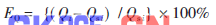 (2)
(2)  (3)
(3)